Guide
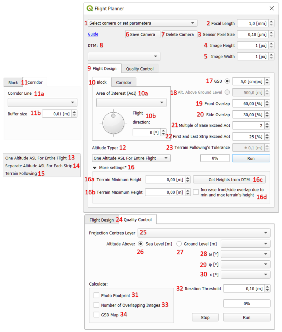
- Select camera or set parameters – list of available cameras. After selecting one of them, camera parameters [2, 3, 4, 5] on the right will be filled in,
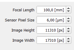
- Focal Length – distance between the lens and the image sensor when the subject is in focus,
- Sensor Pixel Size – called sometimes pixel pitch. It is a distanse from the centre of a pixel to the centre of the adjacent pixel,
- Image Height – number of pixels along track of flight,
- Image Width – number of pixels across track of flight,
- Save Camera – allows the user to save camera parameters that are currently displayed on the right [2, 3, 4, 5]. User needs to enter camera’s name,
- Delete Camera – allows the user to delete camera from the cameras list [1],
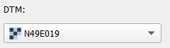
- DTM – place to input Digital Terrain Model in raster format. This layer is required if user wants to design flight in Separate Altitude ASL For Each Strip [14] or Terrain Following [15] mode or to get heights to fulfill Terrain Minimum Height [16a] and Terrain Maximum Height [16b] that are used in One Altitude ASL For Entire Flight [13] mode. This layer is also required if user wants to get outputs of Quality Control [24] panel. DTM can be dowloaded e.g. via SRTM Downloader plugin,
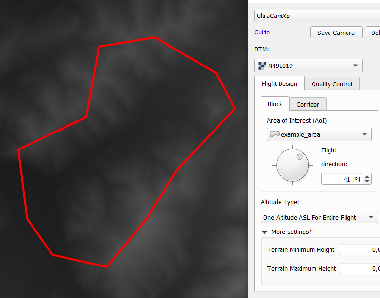
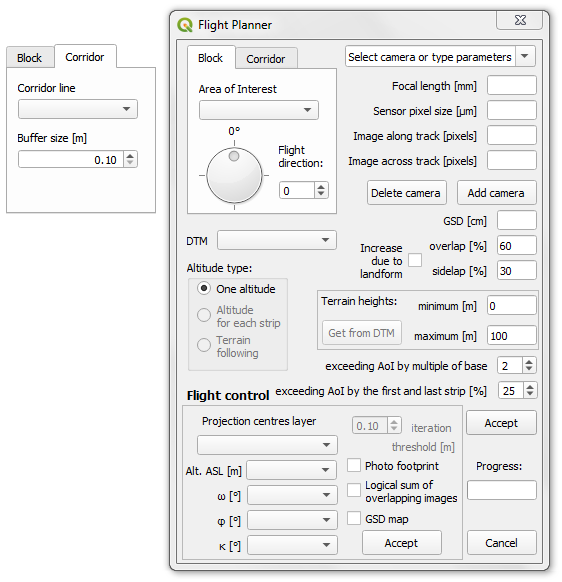
- Flight Design – panel where user can set all the parameters necessary to plan the flight,
- Block – panel that allows to plan block type flight ,
- 10a. Area of Interest (AoI) – polygon vector layer representing the area over which user wants to fly. This layer must be in metric CRS,
- 10b. Flight direction – angle that indicate the direction of strips, set with the dial or spinbox,
- Corridor – panel that allows user to plan corridor type flight,
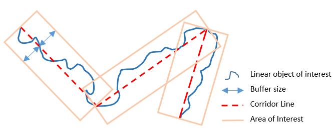
- 11a. Corridor Line – line vector layer that indicates the main axes of a linear object (e.g. river, road, railroad) that user wants to photograph. This layer must be in metric CRS,
- 11b. Buffer size – an invisible Area of Interest with a width of 2 Buffer size will be created around each main axis of the Corridor Line [11a]. This indirectly determines the number of strips for the axis,
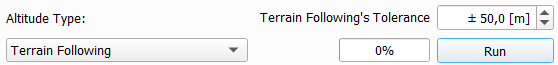
- Altitude Type – user can design flight altitude selecting by one of the three modes:
- One Altitude ASL For Entire Flight – this mode sets one constant flight altitude, that based on the average height of the terrain calculated from Terrain Minimum Height [16a] and Terrain Maximum Height [16b] with added flight altitude derived from GSD [17], Focal Length [2] and Sensor Pixel Size [3]. Only in this mode DTM [8] is not required and user can set Minimum [16a] and Maximum [16b] Terrains Heights by itself,
- Separate Altitude For Each Strip – design for each strip one constant flight altitude that is based on minimum and maximum terrain heights within each strip derived from DTM [8] which is required. This mode DOES NOT use heights from [16a] and [16b],
- Terrain Following – allows the aircraft to follow the altitude of the terrain with a specified tolerance [23]. Only in this mode user can directly indicate constant flight Altitude Above Ground Level [18]. DTM [8] is required.
- More settings – give possibility to set Terrain Heights [16a, 16b] for One Altitude ASL For Entire Flight [13] mode if user for some reason did not load DTM [8],
- 16a. Terrain Minimum Height – minimum height of the terrain within AoI [10a], that user can fulfill by itself if there is no access to DTM [8]
- 16b. Terrain Maximum Height - maximum height of the terrain within AoI [10a], that user can fulfill by itself if there is no access to DTM [8]
- 16c. Get Heights from DTM – however if DTM [8] is loaded user can automatically get Minimum [16a] and Maximum [16b] Terrain Heights that are always used to calculate average height of terrain, but only for One Altitude ASL For Entire Flight [13] mode.
- 16d. Increase front/side overlap – based on GSD [17], Focal Length [2], Sensor Pixel Size [3] and Minimum [16a] and Maximum [16b] Terrain Heights allows user to increase Front Overlap [19] and Side Overlap [20]. The greater the difference between the Minimum [16a] and Maximum [16b] Heights, the greater the increase in Overlaps [19, 20] will be. This feature is designed to help the user in determining sufficient photo coverage,
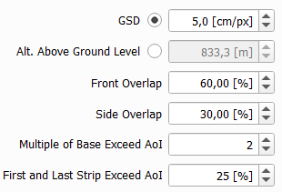
- GSD – Ground Sampling Distance is the distance between two consecutive pixel centers measured on the ground. Based on this value and the Focal Length [2] and Sensor Pixel Size [3], the Altitude Above Ground Level [18] is calculated,
- Alt. Above Ground Level – Altitude AGL is derived from values of GSD [17], Focal Length [2] and Sensor Pixel Size [3]. This value can be fulfill by the user only in Terrain Following [15] mode, because other two methods are aiming on maintain constant altitude above sea level, not the ground level,
- Front Overlap – overlap between two adjacent photos in a strip,
- Side Overlap – overlap between two adjacent strips,
- Multiple of Base Exceed AoI – is the number that specifies the multiple of the longitudinal base (distance between two adjacent centre projections in strip) within which the projection centers will be designed. The Multiple is calcuated from the boundary of the Area of Interest [10a] in outward direction. The image below shows an example for a Multiple of 2:
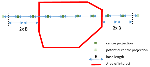
Light-green projection centers lie further than the length of the two bases, so they were not included in the final design.
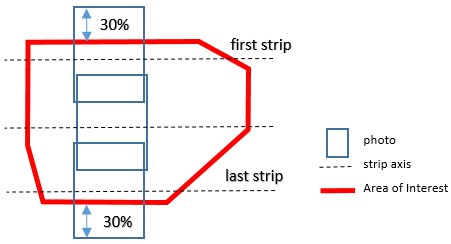
- First and Last Strip Exceed AoI - determines how much of the image (from the first and last strip) will go beyond the Area of Interest [10a]. The following example shows what setting this parameter to 30% means:
- Terrain Following’s Tolerance – parameter that determines how accurately the aircraft will follow the altitude of the terrain. The lower the tolerance, the more accurate the terrain following will be, resulting in more projected waypoints and more changes in the flight trajectory,
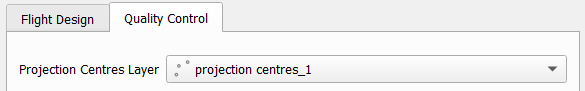
- Quality Control – panel that the user can treat as post-processing. Requires DTM [8] layer and Projection Centers [25] with Exterior Orientation parameters in the attribute table. Allows checking the geometric aspect of the designed (or already made) photogrammetric flight,
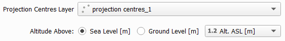
- Projection Centres Layer – is a point layer (must be metric CRS), that must contain attribute table with Exterior Orientation parameters for each photo,
- Altitude Above Sea Level – after indicating the layer of Projection Centers [25], user can choose whether to specify the relative altitude [27] of the projection centers or their absolute altitude,
- Altitude Above Ground Level – if the user cannot specify the Altitude Above Sea Level [26] of the Projection Centers [25] there is an option to indicate their relative altitude,
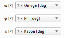
- Omega – an angle that describes rotation of photo around X axis,
- Phi - an angle that describes rotation of photo around Y axis,
- Kappa - an angle that describes rotation of photo around Z axis,
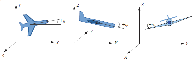
It should be noted that Omega, Phi, Kappa are not the same as Yaw, Pitch, Roll angles.
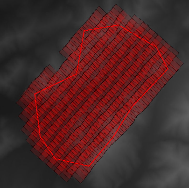
- Photo Footprint – checkbox that allows user to get polygon vector layer representing real ground range of each photo,
- Iteration Threshold – Photo Footprint [31] is calculated in an iterative manner. The calculation is terminated when the distance between the vertex of the photo footprint from the i-th iteration and the previous step is less than the assumed Threshold. The smaller the Threshold, the longer the calculation takes and the more accurately the Photo Footprint [31] is,
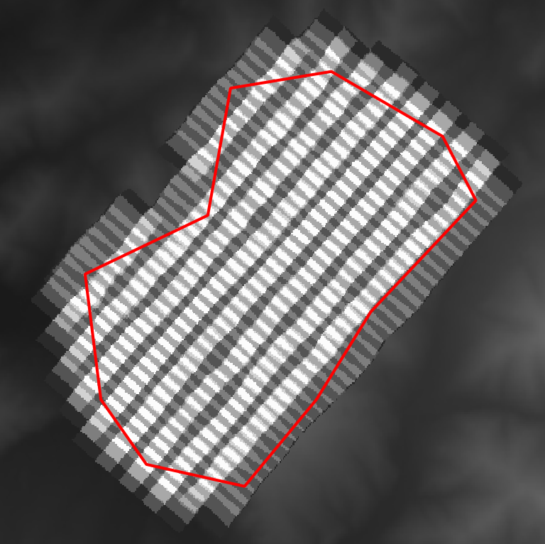
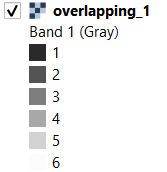
- Number of Overlapping Images - raster form of Photo Footprint [31], which makes it much easier to check the number of photo coverage. The resolution of the layer is the same as that of the DTM [8],
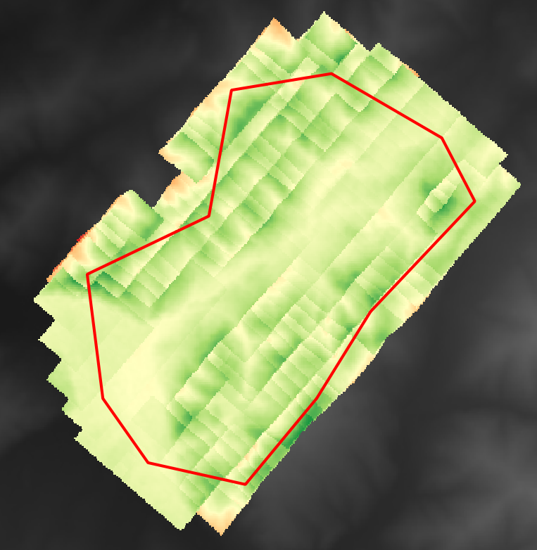
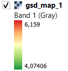
- GSD map - is a raster layer showing the actual ground sampling distance (it gives correct results also for oblique images). The resolution of the layer is the same as that of the DTM [8].
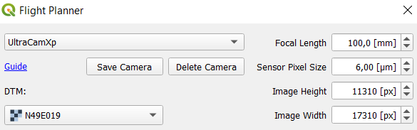
- Set the camera parameters, for example as below
- Load DTM that cover entire Area of Interest
- Load Area of Interest and set Flight Direction, which should follow the longer dimension of the AoI - the smaller number of strips, the better
- Choose Altitude Type and Tolerance if you selected Terrain Following mode. If you have chosen One Altitude For Entire Flight mode you can use More settings panel and get Minimum and Maximum Heights from DTM (then check Increase front/side overlap if you want)
- Set GSD you want to get (or Altitude AGL if Terrain Following mode has been chosen), determine Front Overlap, Side Overlap, Multiple of Base that will exceed AoI and the percentage of images that exceed the Frist and Last Strip
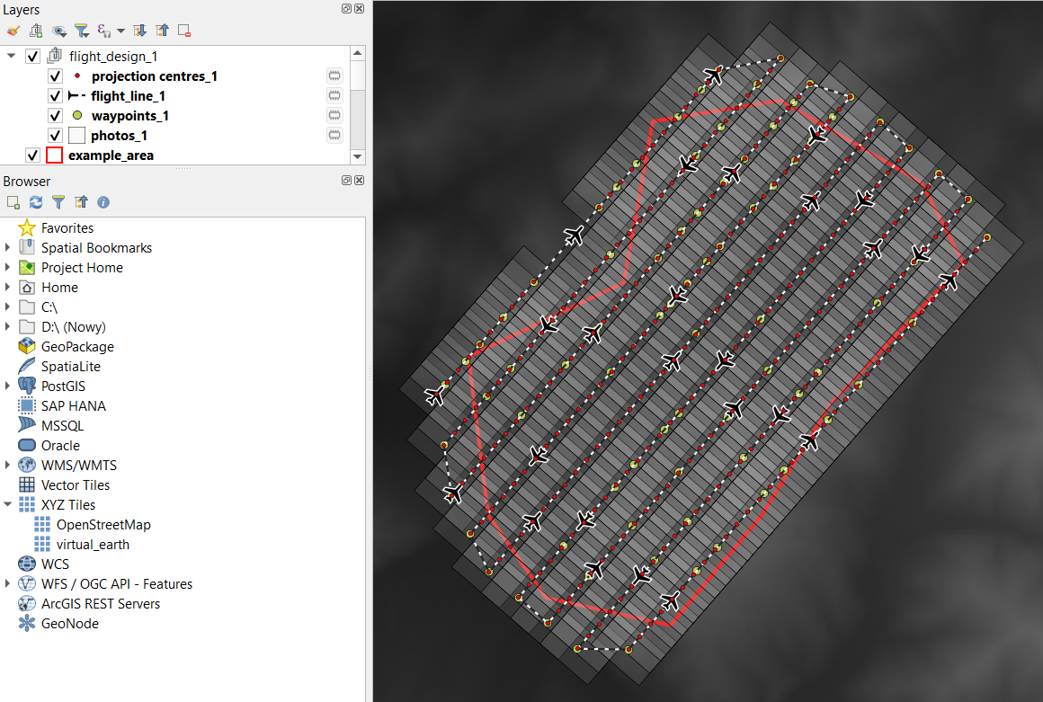
- Click Run and take a look at output layers:
- projection centres
- flight line
- waypoints
- photos
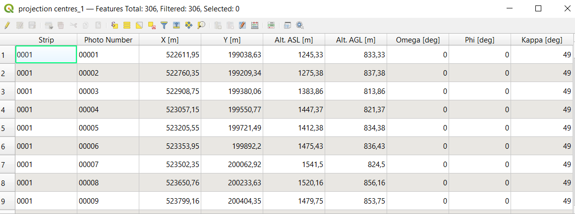
Fragment of attribute table of projection centres layer:
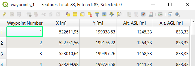
Fragment of attribute table of waypoints layer:
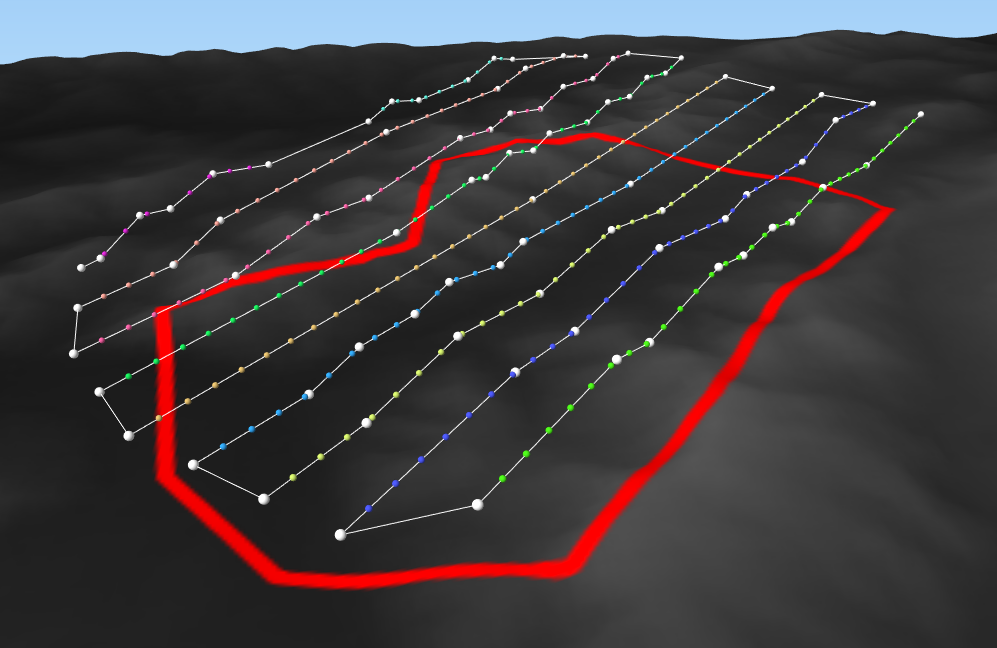
A 3d preview of the designed flight is possible in the Qgis2threejs plugin. White spheres present waypoints, colorful spheres present projections centres for each strip:
For Litchi users @pdfinn has created a tool that can help convert the plugin outputs to Litchi mission: https://github.com/pdfinn/flightplan2litchimission
Once the flight is designed, you can do post-processing and see how well the images will cover the terrain and what is the real GSD.
- Check if the camera parameters are the same as when you designed the flight, load the DTM
- load a layer of projection centers from the designed flight
- Select Altitude Above Sea Level or Above Ground Level and point appropriate field from table attribute
- Select Kappa, Omega and Phi fields from attribute table
- Choose what you want to check - you can mark all three checkboxes or just one. Don't forget to set Iteration Threshold.
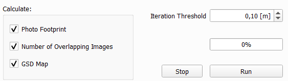
- Click Run and take a look at the result layers:
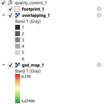
Photo Footprint:
Less accurate than Footprint, but easier to check land coverage Number of Overlapping Images layer:
GSD map:
-
Block tab allows to make a flight plan of block type. You need to:
- provide polygon Area of Interest (*.shp and metric CRS)
- set Flight direction of strips
-
Corridor tab allows to make a flight plan of corridor type. You need to:
- provide Corridor line layer showing main axes of flight (*.shp and metric CRS)
- set the Buffer size of the flight axes, which indirectly determines the number of strips within the axis
- In the upper right side you can choose one of camera from cameras library or type your own parameters:
- Focal length
- Sensor pixel size
- Number of pixels along and across track
- You can save your own camera parameters by Add camera button (necessary saving as .txt in default directory)
- To remove camera from cameras library, just choose the one and click Delete camera
- Below camera section set desirable GSD (Ground Sampling Distance)
- Specify overlap between consecutive photos and sidelap between consecutive strips
- Increase due to landform is the hint as to how much to increase overlap and sidelap due to the differences between the maximum height and minimum height of the terrain
- Maximum and minimum terrain heights in the Area of Interest are the values that affect the calculation of the flight altitude and increasing the overlap/sidelap values.
- If you load raster DTM, the Get from DTM button will become active - it allows you to get minimum and maximum terrain heights automatically.
-
One altitude for the whole project is always available. After loading DTM two more options of planning altitude flight height will become active:
- Altitude for each strip
- Terrain following
- At the end you can specify two margins of exceeding photos beyond the Area of Interest:
- exceeding AoI by multiple of base is the number that specifies the multiple of the longitudinal base (outside the Area of Interest) within which the projection centers will be designed
- exceeding AoI by the first and last strip specifies how big part of the photo (of the first and last strips) will extend out of the area of interest
- Accept button runs calculations. If you choose an option one altitude, flight plan will be design very fast. If you choose altitude for each strip or terrain following it takes much more time
-
Projection centers layer is a point shapefile layer (metric CRS), that must contain attribute table with Exterior Orientation parameters for each photo:
- Alt. ASL is altitude above sea level (fields must be numeric type)
- three angles: Omega, Phi and Kappa (fields must be numeric type)
- Photo footprint allows you to get a vector layer showing the real photos coverage. The coordinates of the layer's vertices are iteratively calculated, so after checking this option you can also specify the iteration threshold. The threshold specifies the maximum allowable distance between the vertices of the previous and current iteration - the smaller the threshold value, the longer the calculations will take, but the result will be more reliable.
- Logical sum of overlapping images is a raster form of the Photo footprint, but it makes it much easier to check how many photos a given place covers. The resolution of result layer is the same as DTM's resolution.
- GSD map is a raster layer showing the real Ground Sampling Distance (it gives a correct results also for oblique images). The resolution of result layer is the same as DTM's resolution.
For all type of Flight Controls you need DTM and specify camera parameters. Cutting the DTM to the smallest possible size (but still covering the expected area of results) significantly reduces the calculation time.
For some type of errors Error_log.txt file in the plugin's directory is created. Sending it to me will be very helpful.